Code Description
Purpose
An executable python package that can calculate dimensions for the main parts of a wastewater treatment plant using inflow quantities and chemical properties.
The main parts and its functions are:
Primary sedimentation tank for settleable solids.
Activated sludge tank for organic matter removal through aeration and filtration.
Secondary sedimentation tank for biomass separation through settlement.
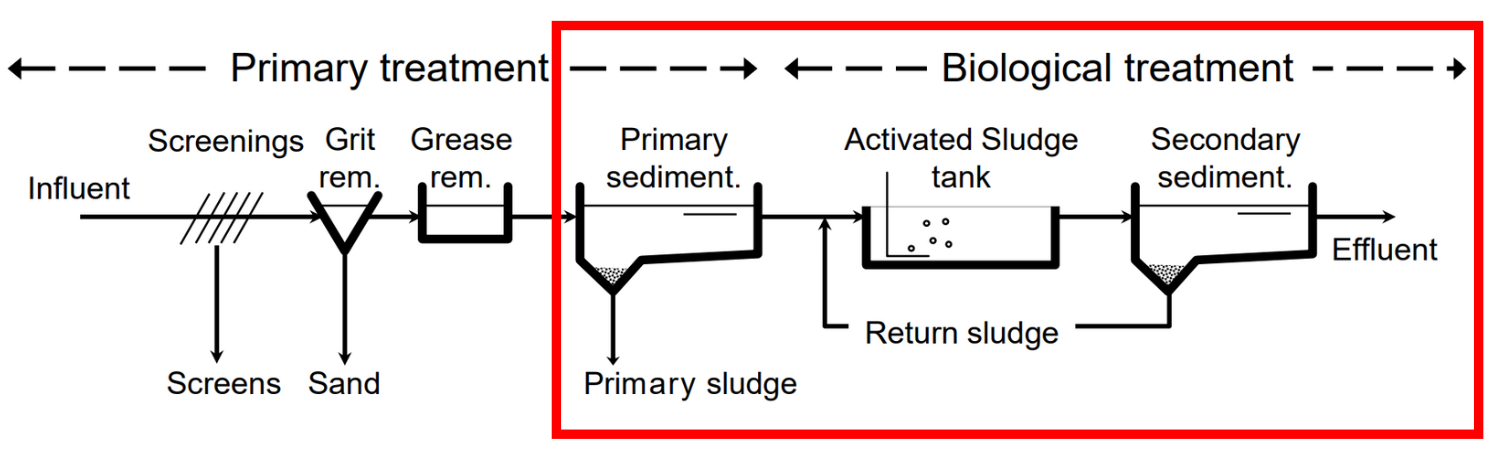
Fig 2. Basic flow scheme of a wastewater treatment plant. (source: Gujer 1999).
Abbreviation |
Description |
Units |
|---|---|---|
Qd,aM |
Daily inflow, annual mean |
m3/d |
QDW,aM |
Dry weather flow as annual mean |
L/s |
QDW,2h,max |
Maximum dry weather flow as 2 hourly mean |
L/s |
QWW,aM |
Wastewater flow as annual mean |
L/s |
Qinf,aM |
Infiltration water flow as annual mean |
L/s |
Qcomb |
Combined wastewater flow |
m3/d |
Bd,BOD5 |
Daily mean biochemical oxygen demand |
kg/d |
Bd,Ntot |
Daily mean total nitrogen load |
kg/d |
Bd,NO3-N |
Daily mean nitrate load |
kg/d |
Bd,Ptot |
Daily mean phosphate load |
kg/d |
Tdim |
Dimensioning temperature |
°C |
Motivation
The ability to design a wastewater treatment plant having only inflow data and some key biological parameters, skipping the tedious, table filled, iterative process of which sedimentation tanks and biological treatment design depend on:
Discharges have a wide range depending on the population equivalents.
Biochemical loads have expected unitary values, but will vary in their total quantities (regarding previous point).
Wide range of tabulated design standards (this varies from country to country), which add tediousness on the path to a size-optimized wastewater treatment plant.
Goals
Fundamental components
The wwtp_design package consists of 8 modules. First, data.py
has been created as a class to import key data values for geometrical
design of a wastewater treatment plant from the input Excel file
input_data.xlsx. The list of inflows and chemical properties shown
above will be used in different modules and classes during running
process. Secondly, general functions and global variables (i.e., tables
of the corresponding standard) have been created in fun.py and
config.py (being this a modifiable module, allowing flexibility,
since regulation values may vary from country to country) respectively.
Thirdly, pri_sed.py, sec_sed.py, and act_sludge.py are
modules where classes have been created to perform the respective
dimensioning of each tank. Last but not least, in main.py 3 Excel
files are generated and logged for each of the corresponding stages.
pri_sed_results.xlsxact_sludge_results.xlsxsec_sed_results.xlsx
Auxiliary components
A class inheritance
ActSludge(InputReader)inact_sludge.py.Creation of another class
PriSed(InputReader)inpri_sed.pythat also inherits, so in total there are 4 classes and 2 of them inherit.Log actions files (info, error, and warning).
info.logerror.logwarning.log
__init__.pyis created in order to get a package.
Input
The input file looks as shown in figure 3. Discharge values are related
to the inflow coming into the projected wastewater treatment plant.
The chemical parameters as well, will mainly be used in combination
with the limit values at the config.py to get other variables
required for design. Units must be respected since these will be
further on converted if needed. The ones seen on the input table are
the most common units utilized for these types of calculation.
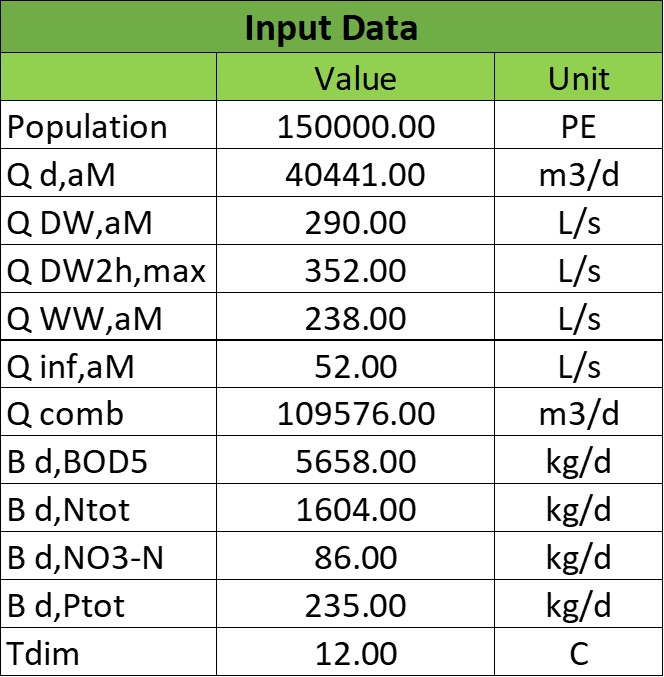
Fig 3. Input data needed for dimensioning. (source: Authors, 2024).
Primary Sedimentation
Rectangular tanks will be used for the primary sedimentation designing process as shown in figure 4.

Fig 4. Rectangular sedimentation tank. (source: Harald Schoenberger 2022).
The focus of primary treatment of wastewater is to reduce the amount of settleable solids and grit that may come into the treatment plant and damage further devices. At figure 5, it can be seen that 90% of settleable solids can be sedimented within ~45 minutes:
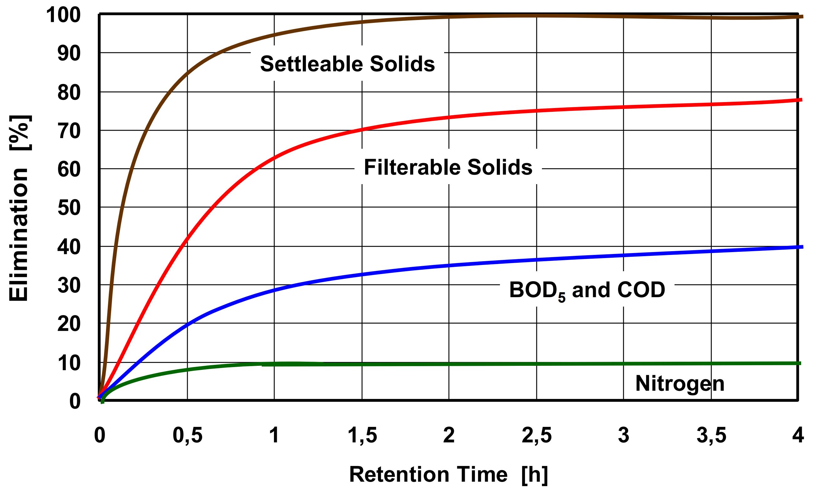
Fig 5. Efficiency of primary sedimentation. (source: ATV-Handbuch 1997a).
For different types of treatments there is an optimal:
Treatment method |
qa [m / h] |
t [min] |
Depth [m] |
|---|---|---|---|
PS combined with activated sludge process (without excess sludge) |
6 |
15 |
1.5 |
PS combined with activated sludge process (with excess sludge) |
2 - 3 |
45 |
2.0 |
PS combined with trickling filter or rotating contactors (with / without excess sludge) |
3 |
30 |
1.5 |
The package has been written to design WWTPs with activated sludge process (with addition of excess sludge) and as can be seen in the retention time, this is exactly 45 minutes, the required to sediment 90% of settleable solids.
Once surface loading (qa) is defined (according to the treatment method) total surface area is calculated with:
Amin = Qcomb / qa
where:
Amin is the total tank surface [ m2 ]
Qcomb is the combined wastewater flow [ m3 / h ]
qa is the surface loading [ m / h ]
The tank surface is the total surface needed for the primary treatment, it must be divided by the number of tanks, which will always initially be 2 for the occasion in which one of them needs to be stopped for maintenance:
Aper tank = Amin / Ntanks
where:
Aper tank is the area per rectangular tank [ m2 ]
Amin is the tank surface [ m2 ]
Ntanks is the number of rectangular tanks [ - ]
From the unitary area, an initial width is selected such that the ratio of width to length is within the established dimensional ratios:
L = Aper tank / W
1 m ≤ W ≤ 10 m
1:10 ≤ W:L ≤ 1:5
where:
L is the length of the rectangular tank [ m ]
Aper tank is the area per tank [ m2 ]
W is the width of the rectangular tank [ m ]
Width cannot be over 10 meters as a rule, due to travelling bridge stability.
The smallest ratio (1:10) in combination with the maximum width (10m) also implicitly limit the maximum surface area per tank, and for this, the package will automatically add another sedimentation tank and recalculate dimensions until dimensional ratio between width and length comply.
Once this finalizes, the total primary sedimentation tank volume is calculated:
Vmin = Ntanks · W · D · L
where:
Vmin is the total tank volume [ m3 ]
Ntanks is the number of rectangular tanks [ - ]
W is the width of the rectangular tank [ m ]
D is the depth of the rectangular tank [ m ]
L is the length of the rectangular tank [ m ]
The result file, pri_sed_results.xlsx, will
look the following way:
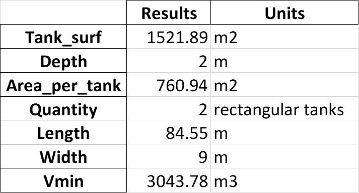
Fig 6. Screenshot of primary sedimentation dimensioning output (source: Authors, 2024).
where:
Tank_surf is the total surface required [ m2 ]
Depth is the depth per primary sedimentation tank [ m ]
Area_per_tank is the area per primary sedimentation tank [ m2 ]
Quantity is the number of primary sedimentation tanks [ - ]
Length is the length per primary sedimentation tank [ m ]
Width is the width per primary sedimentation tank [ m ]
Vmin is the minimum volume required [ m3 ]
Activated Sludge Tank
The activated sludge tank will have a pre-denitrification process and a nitrification process with their respective aeration systems as shown in the figure 7.

Fig 7. Parts of Activated Sludge Tank (source: Authors, 2024).
Below is the step-by-step dimensioning according to ATV-DVWK-A 131E 2000 German Standard:
Convert data loads to concentrations using the following formula:
CXXX or SXXX or XXXX = ( BXXX / Qd,aM ) · 1000
where:
CXXX is the concentration of the parameter XXX in the homogenised sample [ mg / L ]
SXXX is the concentration of the parameter XXX in the filtered sample (0.45 µm membrane filter) [ mg / L ]
XXXX is the concentration of the filter residue (solids), XXXX = CXXX - SXXX [ mg / L ]
BXXX is the load of the parameter XXX [ kg / d ]
Qd,aM is the daily inflow, annual mean [ m3 / d ]
Nitrogen balance must be carried out with the following formulas:
SNH4,`N = CN,IAT - SorgN,EST - SNH4,EST - XorgN,BM
where:
SNH4,`N is the concentration of ammonium nitrogen to be nitrified [ mg / L ]
CN,IAT is the concentration of total nitrogen from the influent to the activated sludge tank [ mg / L ]
SorgN,EST is the concentration of organic nitrogen from the effluent of the secondary sedimentation tank [ mg / L ]
SNH4,EST is the concentration of ammonium nitrogen from the effluent of the secondary sedimentation tank [ mg / L ]
XorgN,BM is the concentration of phosphorus embedded in the biomass [ mg / L ]
SNO3,D = SNH4,N - SNO3,EST
where:
SNO3,D is the concentration of nitrate nitrogen to be denitrified [ mg / L ]
SNH4,N is the concentration of ammonium nitrogen to be nitrified [ mg / L ]
SNO3,EST is the concentration of nitrate nitrogen from the effluent of the secondary sedimentation tank [ mg / L ]
3. Determination of VD / VAT by calculating SN03,D / CBOD,IAT and using the table below:
VD / VAT |
Pre-anoxic zone denitrification and comparable processes |
Simultaneous and intermittent denitrification |
|---|---|---|
0.2 |
0.11 |
0.06 |
0.3 |
0.13 |
0.09 |
0.4 |
0.14 |
0.12 |
0.5 |
0.15 |
0.15 |
where:
VD is the volume of the activated sludge tank used for denitrification [ m3 ]
VAT is the volume of the activated sludge tank [ m3]
Calculation of the required sludge age using the following formulas:
tSS,aerob,dim = SF · 3.4 · 1.103( 15 - T )
where:
tSS,aerob,dim is the aerobic sludge age upon which dimensioning for nitrification is based [ d ]
SF is the safety factor for nitrification [ - ]
T is the temperature for dimensioning [ °C ]
Considering also denitrification:
tSS,dim = tSS,aerob,dim · [ 1 ] / [ 1 - ( VD / VAT ) ]
where:
tSS,dim is the sludge age upon which dimensioning is based [ d ]
tSS,aerob,dim is the aerobic sludge age upon which dimensioning for nitrification is based [ d ]
VD / VAT is the volume ratio from the denitrification tank to activated sludge tank [ - ]
Alternatively, the following table can be used to find the required sludge age.
Treatment target |
VD / VAT |
10 °C - up to 1200 kg/d |
12 °C - up to 1200 kg/d |
10 °C - over 6000 kg/d |
12 °C - over 6000 kg/d |
|---|---|---|---|---|---|
Without nitrification |
5.0 |
5.0 |
4.0 |
4.0 |
|
With nitrification |
10.0 |
8.2 |
8.0 |
6.6 |
|
Nitrification and denitrification |
0.2 |
12.5 |
10.3 |
10.0 |
8.3 |
Nitrification and denitrification |
0.3 |
14.3 |
11.7 |
11.4 |
9.4 |
Nitrification and denitrification |
0.4 |
16.7 |
13.7 |
13.3 |
11.0 |
Nitrification and denitrification |
0.5 |
20.0 |
16.4 |
16.0 |
13.2 |
Sludge stabilization including nitrogen removal |
25.0 |
25.0 |
where:
T is the temperature for dimensioning [ °C ]
Bd,BOD,I is the daily BOD5 load from influent to the wastewater treatment plan [ kg / d ]
(VD / VAT) is the volume ratio from the denitrification tank to activated sludge tank [ - ]
5. Calculation of total excess sludge production by following these steps:
First, the Inhabitant-SS load is extracted from the table below, a retention time after primary sedimentation of 0.5 to 1 h is sufficient. Remember to transform it to concentration.
Parameter |
Raw wastewater |
0.5 to 1.0 h of retention time after PS |
1.5 to 2.0 h of retention time after PS |
|---|---|---|---|
BOD5 |
60 |
45 |
40 |
COD |
120 |
90 |
80 |
SS |
70 |
35 |
25 |
TKN |
11 |
10 |
10 |
P |
1.8 |
1.6 |
1.6 |
where:
BOD5 stands for biochemical oxygen demand
COD stands for chemical oxygen demand
SS stands for suspended solids
TKN stands for total Kjeldahl nitrogen
P stands for phosphorous
Second, calculation of the temperature factor for endogenous respiration:
FT = 1.072( T - 15 )
where:
FT is a temperature factor [ - ]
T is the temperature for dimensioning [ °C ]
Third, calculation of the sludge production from carbon removal:
SPd,C = Bd,BOD · { [0.75] + [ 0.6 · ( XSS,IAT / CBOD,IAT ) ] - [ ( (1-0.2) · 0.17 · 0.75 · tss,dim · FT ) / ( 1 + 0.17 · tss,dim · FT ) ] }
where:
SPd,C is the daily sludge production from carbon removal [ kg / d ]
Bd,BOD is the daily BOD5 load [ kg / d ]
XSS,IAT is the concentration of suspended solids from the influent to the activated sludge tank [ mg / L ]
CBOD,IAT is the concentration of BOD5 from the influent to the activated sludge tank [ mg / L ]
tss,dim is the sludge age upon which dimensioning is based [ d ]
FT is a temperature factor [ - ]
Alternatively, the following table can be used to find the specific sludge production SPC,BOD [ kg SS / kg BOD5 ] at 10° to 12° C, and, then, multiply by the influent BOD5 load to find the sludge production from carbon removal.
XSS,IAT / CBOD,IAT |
4 |
8 |
10 |
15 |
20 |
25 |
|---|---|---|---|---|---|---|
0.4 |
0.79 |
0.69 |
0.65 |
0.59 |
0.56 |
0.53 |
0.6 |
0.91 |
0.81 |
0.77 |
0.71 |
0.68 |
0.65 |
0.8 |
1.03 |
0.93 |
0.89 |
0.83 |
0.80 |
0.77 |
1.0 |
1.15 |
1.05 |
1.01 |
0.95 |
0.92 |
0.89 |
1.2 |
1.27 |
1.17 |
1.13 |
1.07 |
1.04 |
1.01 |
where:
XSS,IAT is the concentration of suspended solids from the influent to the activated sludge tank [ mg / L ]
CBOD,IAT s the concentration of BOD :sub:5 from the influent to the activated sludge tank [ mg / L ]
Next, the phosphorus balance is calculated by first extracting the CP,EST according to the size class in the following table:
Size class |
COD [ mg / L ] |
BOD [ mg / L ] |
NH4-N [ mg / L ] |
Ntot [ mg / L ] |
Ptot [ mg / L ] |
|---|---|---|---|---|---|
1 (< 60 kgBOD5/d in raw water) |
150 |
40 |
|||
2 (60 - 300 kgBOD5/d in raw water) |
110 |
25 |
|||
3 (300 - 600 kgBOD5/d in raw water) |
90 |
20 |
10 |
||
4 (600 - 6000 kgBOD5/d in raw water) |
90 |
20 |
10 |
18 |
2 |
5 (> 6000 kgBOD5/d in raw water) |
75 |
15 |
10 |
13 |
1 |
XP,Prec = CP,IAT - CP,EST - XP,BM - XP,BioP
where:
XP,Prec is the concentration of phosphorus removed by simultaneous precipitation [ mg / L ]
CP,IAT is the concentration of phosphorus from the influent to the activated sludge tank [ mg / L ]
CP,EST is the concentration of phosphorus from the effluent of the secondary sedimentation tank [ mg / L ]
XP,BM is the concentration of phosphorus embedded in the biomass [ mg / L ]
XP,BioP is the concentration of phosphorus removed with biological excess phosphorus removal process [ mg / L ]
Now, the excess sludge production is calculated from the phosphorous removal.
SPd,P = { [ QDW ] · [ ( 3 · XP,BioP ) + (6.8 · XP,Prec,Fe ) + (5.3 · XP,Prec,Al ) ] } / { 1000 }
where:
SPd,P is the daily sludge production from phosphorus removal [ kg / d ]
QDW is the wastewater inflow with dry weather [ m3 / d ]
XP,BioP is the concentration of phosphorus removed with biological excess phosphorus removal process [ mg / L ]
XP,Prec,Fe is the concentration of phosphorus removed by simultaneous precipitation using iron [ mg / L ]
XP,Prec,Al is the concentration of phosphorus removed by simultaneous precipitation using aluminium [ mg / L ]
Finally, the total excess sludge production is calculated:
SPd = SPd,C + SPd,P
where:
SPd is the sludge produced in an activated sludge plant [ kg / d ]
SPd,C is the daily sludge production from carbon removal [ kg / d ]
SPd,P is the daily sludge production from phosphorus removal [ kg / d ]
6. Calculation of the mass of suspended solids in the activated sludge tank:
MSS,AT = tSS,dim · SPd
where:
MSS,AT is the mass of suspended solids in the activated sludge tank [ kg ]
tSS,dim is the sludge age upon which dimensioning is based [ d ]
SPd is the sludge produced in an activated sludge plant [ kg / d ]
Calculation of required tank volumes:
VAT = MSS,AT/ SSAT
where:
VAT is volume of the activated sludge tank [ m3 ]
MSS,AT is the mass of suspended solids in the activated sludge tank [ kg ]
SSAT is the suspended solids concentration in the activated sludge tank [ kg / m3 ]
VD = ( VD / VAT ) · VAT
where:
VD / VAT is the volume ratio from the denitrification tank to activated sludge tank [ - ]
VAT is volume of the activated sludge tank [ m3 ]
VN = VAT - VD
where:
VN is the volume of the activated sludge tank used for nitrification [ m3 ]
VAT is volume of the activated sludge tank [ m3 ]
VD is the volume of the activated sludge tank used for denitrification [ m3 ]
8. Calculation of the total recirculation ratio at pre-anoxic zone denitrification process:
RC = [ ( SNH4,N ) / ( SNO3,EST ) ] - [ 1 ]
where:
RC is the total recirculation ratio at pre-anoxic zone denitrification process [ - ]
SNH4,N is the concentration of ammonium nitrogen to be nitrified [ mg / L ]
SNO3,EST is the concentration of nitrate nitrogen from the effluent of the secondary sedimentation tank [ mg / L ]
nD ≤ [ 1 ] - [ ( 1 ) / ( 1 + RC ) ]
where:
nD is he maximum possible efficiency of denitrification [ - ]
RC is the total recirculation ratio at pre-anoxic zone denitrification process [ - ]
9. Calculation of fC and fN by using the table below:
Peak factors |
4 |
6 |
8 |
10 |
15 |
25 |
|---|---|---|---|---|---|---|
fC and fN |
1.30 |
1.25 |
1.20 |
1.20 |
1.15 |
1.10 |
fN for <= 1200 kgBOD5 / d |
2.50 |
2.00 |
1.50 |
|||
fN for >= 6000 kgBOD5 / d |
2.00 |
1.80 |
1.50 |
Design of aeration system:
OUd,C = { Bd,BOD } · { [ 0.56 ] + [ ( 0.15 · tSS,dim · FT ) / ( 1 + 0.17 · tSS,dim · FT ) ] }
where:
OUd,C is the daily oxygen uptake for carbon removal [ ( kg O2 ) / d ]
Bd,BOD is the daily BOD5 load [ kg / d ]
tSS,dim is the sludge age upon which dimensioning is based [ d ]
FT is a temperature factor [ - ]
OUd,N = [ ( QDW ) · ( 4.3 ) · ( SNO3,D - SNO3,IAT + SNO3,EST ) ] / [ 1000 ]
where:
OUd,N is the daily oxygen uptake for nitrification [ ( kg O2 ) / d ]
QDW is the wastewater inflow with dry weather [ m3 / d ]
SNO3,D is the concentration of nitrate nitrogen to be denitrified [ mg / L ]
SNO3,IAT is the concentration of nitrate nitrogen from the influent to the activated sludge tank [ mg / L ]
SNO3,EST is the concentration of nitrate nitrogen from the effluent of the secondary sedimentation tank [ mg / L ]
OUd,D = [ ( QDW ) · ( 2.9 ) · ( SNO3,D ) ] / [ 1000 ]
where:
OUd,D is the daily oxygen uptake for carbon removal which is covered by denitrification [ ( kg O2 ) / d ]
QDW is the wastewater inflow with dry weather [ m3 / d ]
SNO3,D is the concentration of nitrate nitrogen to be denitrified [ mg / L ]
OUh = [ ( fC ) · ( OUd,C - OUd,D ) + ( fN ) · OUd,N ) ] / [ 24 ]
where:
OUh is the hourly oxygen uptake rate [ ( kg O2 ) / d ]
fC is the peak factor for carbon respiration [ - ]
fN is the peak factor for ammonium oxidation [ - ]
OUd,C is the daily oxygen uptake for carbon removal [ ( kg O2 ) / d ]
OUd,D Daily oxygen uptake for carbon removal which is covered by denitrification [ ( kg O2 ) / d ]
OUd,N is the daily oxygen uptake for nitrification [ ( kg O2 ) / d ]
Below is a screenshot of the output that would be obtained in a .xlsx file if everything runs smoothly:
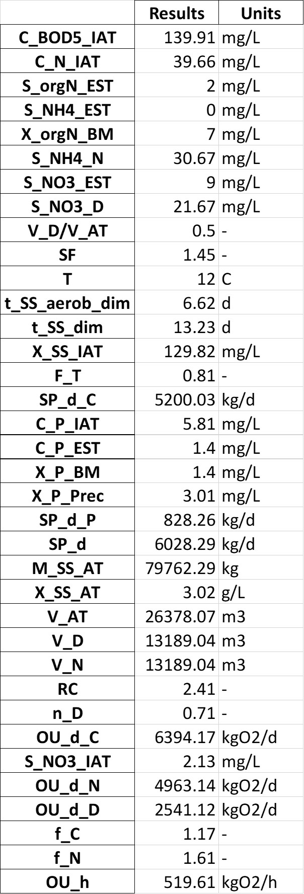
Fig 8. Activated sludge dimensioning output (source: Authors, 2024).
where:
C_BOD5_IAT is the concentration of BOD5 from the influent to the activated sludge tank [ mg / L ]
C_N_IAT is the concentration of total nitrogen from the influent to the activated sludge tank [ mg / L ]
S_orgN_EST is the concentration of organic nitrogen from the effluent of the secondary sedimentation tank [ mg / L ]
S_NH4_EST is the concentration of ammonium nitrogen from the effluent of the secondary sedimentation tank [ mg / L ]
X_orgN_BM is the concentration of organic nitrogen embedded in the biomass [ mg / L ]
S_NH4_N is the concentration of ammonium nitrogen to be nitrified [ mg / L ]
S_NO3_EST is the concentration of nitrate nitrogen from the effluent of the secondary sedimentation tank [ mg / L ]
S_NO3_D is the concentration of nitrate nitrogen to be denitrified [ mg / L ]
V_D/V_AT is the volume ratio, denitrification tank to aeration tank [ - ]
SF is the safety factor for nitrification [ - ]
T is the temperature for dimensioning [ °C ]
t_SS_aerob_dim is the aerobic sludge age upon which dimensioning for nitrification is based [ days ]
t_SS_dim is the sludge age upon which dimensioning is based [ days ]
X_SS_IAT is the suspended solids concentration from the influent to the activated sludge tank [ mg / L ]
F_T is the temperature factor for endogenous respiration [ - ]
SP_d_C is the daily sludge production from carbon removal [ kg / d ]
C_P_IAT is the concentration of phosphorus from the influent to the activated sludge tank [ mg / L ]
C_P_EST is the concentration of phosphorus from the effluent of the secondary sedimentation tank [ mg / L ]
X_P_BM is the concentration of phosphorus embedded in the biomass [ mg / L ]
X_P_Prec is the concentration of phosphorus removed by simultaneous precipitation [ mg / L ]
SP_d_P is the daily sludge production from phosphorus removal [ kg / d ]
SP_d is the daily waste activated sludge production (solids) [ kg / d ]
M_SS_AT is the mass of suspended solids in the activated sludge tank [ kg ]
X_SS_AT is the suspended solids concentration in the activated sludge tank [ g / L ]
V_AT is the volume of the activated sludge tank [ m3 ]
V_D is the volume of activated sludge tank destined to denitrification [ m3 ]
V_N is the volume of activated sludge tank destined to nitrification [ m3 ]
RC is the total recirculation ratio at pre-anoxic zone denitrification process [ - ]
n_D is the maximum denitrification efficiency [ - ]
OU_d_C is the daily oxygen uptake for carbon removal [ kgO2 / d ]
S_NO3_IAT is the concentration of nitrate nitrogen from the influent to the activated sludge tank [ mg / L ]
OU_d_N is the daily oxygen uptake for nitrification [ kgO2 / d ]
OU_d_D is the daily oxygen uptake for carbon removal which is covered by denitrification [ kgO2 / d ]
f_C is the peak factor for carbon respiration [ - ]
f_N is the peak factor for ammonium oxidation [ - ]
OU_h is the oxygen uptake rate (hourly) [ kgO2 / h ]
Secondary Sedimentation
The design of the secondary sedimentation tank was made considering the following criteria: circular tanks with horizontal flow and scraper facilities as shown in figure 9.

Fig 9. Main directions of flow and functional tank zones of horizontal flow circular secondary sedimentation tanks. (source: ATV-DVWK-A 131E 2000).
Below is the step-by-step dimensioning according to ATV-DVWK-A 131E 2000 German Standard:
1. From the table below the SVI (Sludge Volume Index) is extracted according to the design criteria, in our case a nitrification and denitrification target treatment will be performed. Plus, it is recommended to take an average value.
Treatment target |
Favourable (ml/g) |
Unfavourable (ml/g) |
|---|---|---|
Without nitrification |
100 - 150 |
120 - 180 |
Nitrification and denitrification |
100 - 150 |
120 - 180 |
Sludge stabilization |
75 - 120 |
100 - 150 |
2. Now, the thickening time must be extracted according to the type of treatment, with denitrification in our case. From experience, it is advisable to choose the minimum values of the range because with long time sludge flocs degrades, gas bubbles are formed, and, therefore, sludge rises.
Type of wastewater treatment |
Thickening time (h) |
|---|---|
Activated sludge plants without nitrification |
1.5 - 2.0 |
Activated sludge plants with nitrification |
1.0 - 1.5 |
Activated sludge plants with denitrification |
2.0 - (2.5) |
3. Calculation of the suspended solids concentration in the bottom sludge, return sludge, and activated sludge tank:
SSBS = ( 1000 / SVI ) · tTh1/3
where:
SSBS is the suspended solids concentration in the bottom sludge [ g / L ]
SVI is the sludge volume index [ mL/ g ]
tTh is the thickening time [ h ]
SSRS = 0.7 · SSBS
where:
SSRS is the suspended solids concentration of the return sludge [ g / L ]
SSBS is the suspended solids concentration in the bottom sludge [ g / L ]
SSAT = ( RS · SSRS ) / ( 1 + RS )
where:
SSAT is the suspended solids concentration in the activated sludge tank [ g / L ]
SSRS is the suspended solids concentration in the bottom sludge [ g / L ]
RS is the return sludge ratio always 0.75 [ - ]
Calculation of the surface overflow rate and tank surface area:
qA = qSV / DSV
where:
qA is the surface overflow rate [ m / h ]
qSV is the sludge volume loading rate [ L / ( m2 · h ) ]
qSV ≤ 500 for [ L / ( m2 · h ) ] for XSS,EST ≤ 20 [ mg / L ]
DSV is the diluted sludge volume [ mL / L ]
DSV = SSAT · SVI
SSAT is the suspended solids concentration in the activated sludge tank [ g / L ]
SVI is the sludge volume index [ mL / g ]
AST = Qcomb / qA
where:
AST is the secondary sedimentation tank surface area [ m2 ]
Qcomb is the combined wastewater flow [ m3 / h ]
qA is the surface overflow rate [ m / h ]
5. Calculation of the different depths in the secondary sedimentation tank:
h1 = 0.5
where:
h1 is the clean water zone it is a safety zone with a minimum depth of 0.5 [ m ]
h2 = [ 0.5 · qA · ( 1 + RS ) ] / [ 1 - ( DSV / 1000 ) ]
where:
h2 is the separation/return flow zone [ m ]
qA is the surface overflow rate [ m / h ]
RS is the return sludge ratio always 0.75 [ - ]
DSV is the diluted sludge volume [ mL / L ]
h3 = [ 1.5 · 0.3 · qSV · ( 1 + RS ) ] / [ 500 ]
where:
h3 is the density flow and storage zone [ m ]
RS is the return sludge ratio always 0.75 [ - ]
qSV is the sludge volume loading rate [ L / ( m2 · h ) ]
h4 = [ SSAT · qA · ( 1 + RS ) · tTh ] / [ SSBS ]
where:
h4 is the thickening and sludge removal zone [ m ]
SSAT is the suspended solids concentration in the activated sludge tank [ g / L ]
qA is the surface overflow rate [ m / h ]
RS is the return sludge ratio always 0.75 [ - ]
tTh is the thickening time [ h ]
SSBS is the suspended solids concentration in the bottom sludge [ g / L ]
htot = h1 + h2 + h3 + h4
where:
h1 is the clean water zone [ m ]
h2 is the separation/return flow zone [ m ]
h3 is the density flow and storage zone [ m ]
h4 is the thickening and sludge removal zone [ m ]
Below is a screenshot of the output that would be obtained in a .xlsx file if everything runs smoothly:
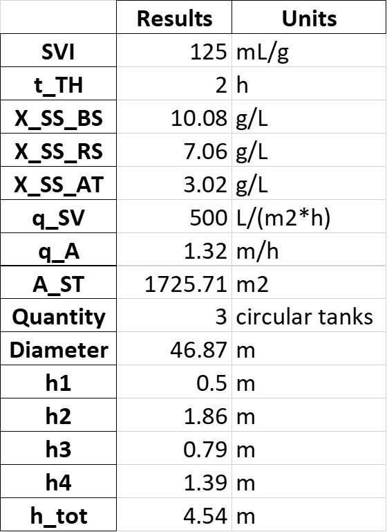
Fig 10. Secondary sedimentation dimensioning output (source: Authors, 2024)
where:
SVI is the sludge volume index [ mL / g ]
t_TH is the thickening time of the sludge in the secondary sedimentation tank [ h ]
X_SS_BS is the suspended solids concentration in the bottom sludge of secondary sedimentation tanks [ g / L ]
X_SS_RS is the suspended solids concentration of the return (activated) sludge [ g / L ]
X_SS_AT is the suspended solids concentration in the activated sludge tank [ g / L ]
q_SV is the sludge volume surface loading rate of secondary sedimentation tanks [ L / ( m2 · h ) ]
q_A is the surface overflow rate of secondary sedimentation tanks [ m / h ]
A_ST is the surface area of secondary sedimentation tanks [ m2 ]
Quantity is the number of circular secondary sedimentation tanks required [ - ]
Diameter is the tank diameter [ m ]
h1 is the depth of the clear water zone in secondary sedimentation tanks [ m ]
h2 is the depth of the separation zone / return flow zone in secondary sedimentation tanks [ m ]
h3 is the depth of the density flow and storage zone in secondary sedimentation tanks [ m ]
h4 is the depth of the sludge thickening and removal zone in secondary sedimentation tanks [ m ]
h_tot is the total water depth in the secondary sedimentation tank (sum of previous 4 heights) [ m ]